
Table Of Contents
DC-DC converters power individual circuits throughout the system. While each circuit may perform well on the test bench, the overall system performance often does not match the performance of the individual circuits. Why? There are many potential causes, but the overall grounding system of each circuit in the system is the primary cause. Designers need to be very clear about how each circuit is grounded and whether there are ground loops in the system.
A ground loop occurs when there is more than one connection to ground between two circuits and/or systems. The repeated ground paths are equivalent to forming a loop antenna that receives interface signals (current is converted to voltage through ground resistance). The consequence of receiving voltages induced by the ground loop is that the system ground reference voltage is unstable as the induced voltages are superimposed. These induced noise voltages become part of the overall system response!
In addition, ground loops form a common line that causes ground currents to return to the system ground pole origin through more than one path. For example, the power supplies of multiple computers are connected to each other through the ground in a common office wiring configuration, but they can also be connected through data communication wiring. Therefore, computers are often connected to each other through more than one ground path. When there are multiple ground paths between multiple computers, the configuration formed is called a “ground loop”. Whenever a ground loop occurs, the ground reference point will receive superimposed signals, forming system interference and noise.
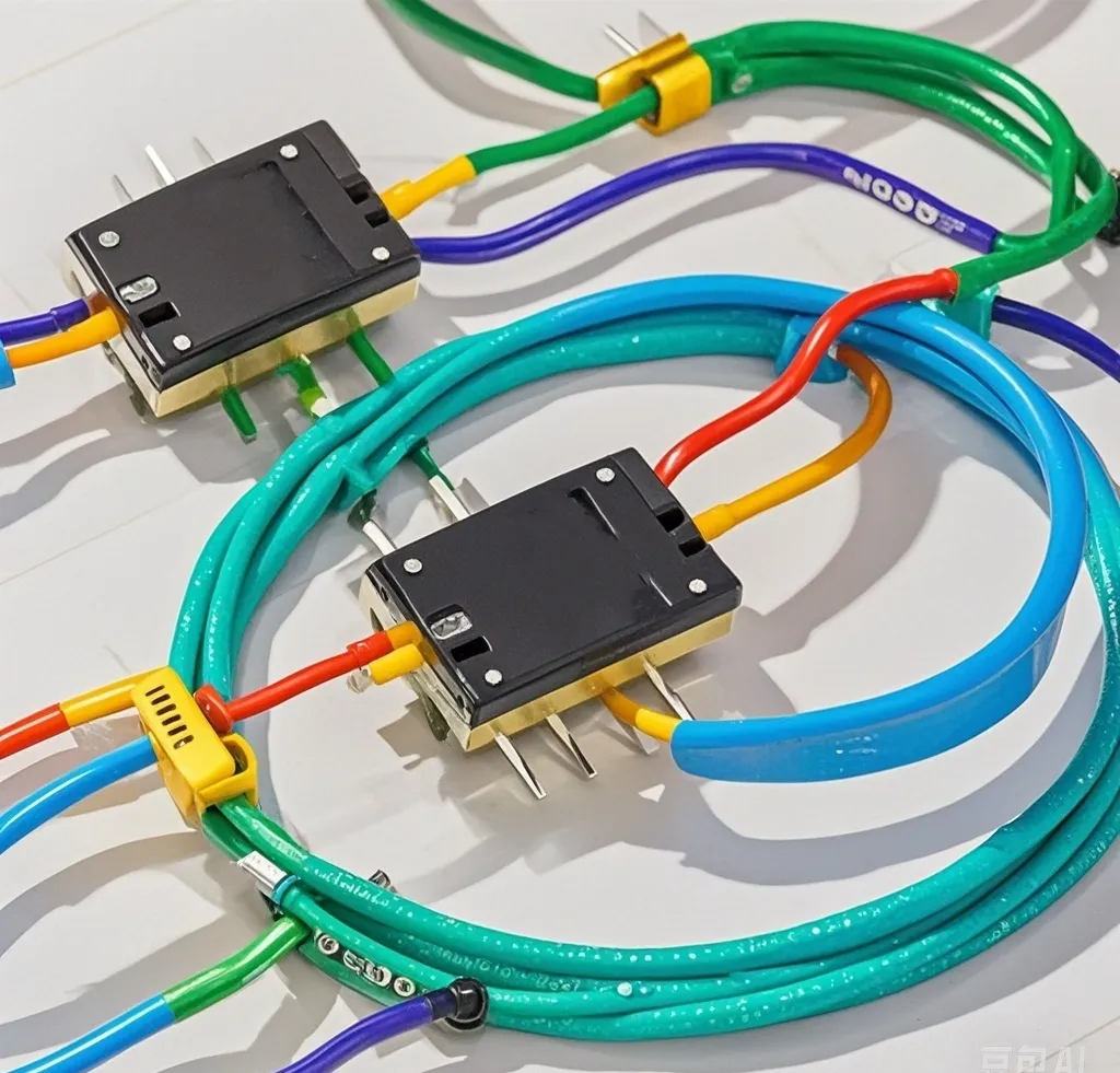
Ground loops can occur in measurement, communication, or video systems when some components in the system are powered by a different ground than other components in the system, or when two circuits in the system are at different ground potentials. Typically, the difference in potential between ground connections causes current to flow. This modulates the circuit input, causing other signals to appear where the input would normally be.
Since there is a voltage difference between instruments, the signal in the interconnecting wires will add this voltage difference to the signal, causing the wires to “hum” with voltage. This is one reason why 60 Hz noise is heard in audio signals (or horizontal interference appears in video signals). Another problem is current flowing in the ground wire of the signal cable. This current can also be carried into the cable and equipment. Designers always pay attention to grounding at the ground end, but often fail to optimize the design to eliminate the sensitivity of the noise floor. Therefore, it is essential to properly design the grounding within the system to ensure that ground loop currents do not cause problems in the system.
As another example, ground loops are a common problem when multiple audio-visual system components are connected together. Common noise in audio systems is often the result of ground loop problems. Also, audible “hum” is a typical ground loop problem (depending on the frequency of the AC mains voltage used in the country, of course). Of course, the most common example of a ground loop problem is a system using an instrument connected to an outlet and another instrument connected to a differently grounded outlet elsewhere in the room.
Ideally, each system in a room should be connected to the same ground, and the signal/antenna network should ultimately be connected to the same ground point. This is ideal because the grounds of the system and each instrument are connected point-to-point (central ground star pattern) from the same ground reference. In this case, it must be considered that some devices (and systems) are also connected by shielded wires. Current flows from one device through the ground wire to another device and then returns to the first device through the shield wire. This loop can also pick up interference from nearby magnetic fields and RF transmitters (such as mobile phones). As a result, amplified unwanted signals are heard. Incidentally, ground loops are not a problem if:
(1) The wire in the loop does not carry current;
(2) The loop is not exposed to external changing magnetic fields;
(3) There is no RF interference nearby.
If there is current flowing in the ground wire, noise interference will be generated when there is a certain potential difference. In addition, a small voltage difference will also add noise to the signal. This situation will cause audio hum, video interference images and computer network transmission errors.
The ground loop problem is an issue that needs to be focused on in the design of DC-DC converters. By adopting single-point grounding, isolation technology, optimizing grounding layout, and using filters, the ground loop problem can be effectively solved and the performance and reliability of the system can be improved. In actual design, the appropriate solution should be selected according to the specific application requirements and fully tested and verified. Good analog system design, analog system test and measurement require careful design of system ground channels to avoid ground loops.